breadboard passive lv filter | Passive Filter Circuits : 4 Steps breadboard passive lv filter Thus far we have seen that simple first-order RC low pass filters can be made by connecting a single resistor in series with a single capacitor. This single-pole arrangement gives us a roll-off slope of -20dB/decade attenuation of frequencies above the cut-off point at ƒ-3dB. However, sometimes in filter circuits this -20dB/decade (-6dB/octave) . See more Offering reversible options and a variety of widths, the selection is versatile, catering to every woman's unique style. Accentuate the waistline for a flattering fit; opt for thinner belts if you have a short torso or wider belts for a longer torso. Pair with women's shoes and designer bucket bags to compliment any ensemble. The Art of Perfection
0 · Passive Low Pass Filter
1 · Passive Filter Circuits : 4 Steps
Men's Belts. In a refined approach to dressing, a selection of belts for Men exudes a modern elegance. Revitalizing the emblematic LV Logo, these creations exalt the signature sophistication of the Maison in timeless colorways. Saint Germain 35mm Belt. LV City Pin 35mm Belt. LV Shadow 40mm Reversible Belt. LV Line 40mm Reversible Belt.
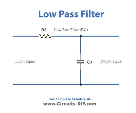
A simple passive RC Low Pass Filter or LPF, can be easily made by connecting together in series a single Resistor with a single Capacitor as . See moreA Low Pass Filter circuit consisting of a resistor of 4k7Ω in series with a capacitor of 47nF is connected across a 10v sinusoidal supply. Calculate the . See more
We can see from the results above, that as the frequency applied to the RC network increases from 100Hz to 10kHz, the voltage dropped across the capacitor and therefore the output voltage ( VOUT) from the circuit decreases from 9.9v to 0.718v. By plotting the networks output voltage against different values of input frequency, the . See moreThus far we have seen that simple first-order RC low pass filters can be made by connecting a single resistor in series with a single capacitor. This single-pole arrangement gives us a roll-off slope of -20dB/decade attenuation of frequencies above the cut-off point at ƒ-3dB. However, sometimes in filter circuits this -20dB/decade (-6dB/octave) . See moreSo to summarize, the Low Pass Filter has a constant output voltage from D.C. (0Hz), up to a specified Cut-off frequency, ( ƒC ) point. This cut-off frequency point is 0.707 or -3dB ( dB = –20log*VOUT/IN) of the voltage gain allowed to pass. The frequency range “below” this cut-off point ƒC is generally known as the Pass Band as the input signal is . See more
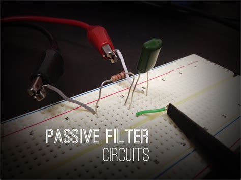
This instructable is intended to show you how to make several different filter circuits, in .Passive RC filters “filter-out” unwanted signals as they separate and allow to pass only those sinusoidal input signals based upon their frequency with the most simple being passive low pass filter network.This instructable is intended to show you how to make several different filter circuits, in particular, low pass and high pass filters, along with a discussion of notch/trap filters and bandpass filters. Essentially, a passive RC filter is a circuit composed of resistors (R) and capacitors (C) working together to provide frequency filtering. In other words, these components collaborate to filter out specific frequencies, tailoring the output signal .
These days though, one can design active, capacitor-only EQs and filters that perform incredibly well, and one can also design LC, mostly passive EQs and filters with modern makeup gain amps that also perform extremely well. Here is a simple LC filter you asked about. I just grabbed an inductor and cap out of the drawer and stuck them onto a breadboard. There was no attempt to calculate or measure the components and the VNA isn't calibrated. The only goal is to show you a simple LCish network acting as a lowpass.
This tutorial shows how to build and test 3rd Order Butterworth Active Low Pass Filter with Sallen-Key topology using LM358 op-amp on breadboard. ee-diary Microcontrollers A passive low pass filter is a designed using passive components. Here is basic guide about passive low pass filter along with examples and applications. I have a 10Mhz OCXO and I want to design a low pass filter to apply at its output. The reason for that is that besides the foundamental frequency (10Mhz) I can measure harmonics as well. I've never designed a filter before.
A typical 5th order filter would be decomposed into dual 2nd-order filters (giving 4 poles) and a separate passive 1rst order. Placing that passive stage first is good way to keep very high frequencies out of the opamp 2nd order building blocks. Walt Jung explains why this is . I am designing a second order low pass filter to filter a 0-10V signal from a sensor. The theory states that there are two possibilities for an active low-pass filter; the Sallen-Key toplogie and the Multiple Feedback topology. However, I wonder why .

Passive RC filters “filter-out” unwanted signals as they separate and allow to pass only those sinusoidal input signals based upon their frequency with the most simple being passive low pass filter network.This instructable is intended to show you how to make several different filter circuits, in particular, low pass and high pass filters, along with a discussion of notch/trap filters and bandpass filters. Essentially, a passive RC filter is a circuit composed of resistors (R) and capacitors (C) working together to provide frequency filtering. In other words, these components collaborate to filter out specific frequencies, tailoring the output signal .
Passive Low Pass Filter
These days though, one can design active, capacitor-only EQs and filters that perform incredibly well, and one can also design LC, mostly passive EQs and filters with modern makeup gain amps that also perform extremely well. Here is a simple LC filter you asked about. I just grabbed an inductor and cap out of the drawer and stuck them onto a breadboard. There was no attempt to calculate or measure the components and the VNA isn't calibrated. The only goal is to show you a simple LCish network acting as a lowpass.
michael kors sloan large shoulder bag gray
This tutorial shows how to build and test 3rd Order Butterworth Active Low Pass Filter with Sallen-Key topology using LM358 op-amp on breadboard. ee-diary Microcontrollers A passive low pass filter is a designed using passive components. Here is basic guide about passive low pass filter along with examples and applications.
I have a 10Mhz OCXO and I want to design a low pass filter to apply at its output. The reason for that is that besides the foundamental frequency (10Mhz) I can measure harmonics as well. I've never designed a filter before. A typical 5th order filter would be decomposed into dual 2nd-order filters (giving 4 poles) and a separate passive 1rst order. Placing that passive stage first is good way to keep very high frequencies out of the opamp 2nd order building blocks. Walt Jung explains why this is .
Passive Filter Circuits : 4 Steps

Off the Shoulder Sweater | US fashion | The Sweetest Thing. Feb 6, 2021 - Explore Rasha Moursy's board "LV belt outfits" on Pinterest. See more ideas about lv belt, outfits, .
breadboard passive lv filter|Passive Filter Circuits : 4 Steps


